 |

Submitted by , posted on 22 December 2004
|
 |

Image Description, by

Yep, another Terrain Engine...
I know, I know, at least one hundred IOTDs were about that.
So what is special about this one? Well you’re the judges...
Hardware rendering of the terrain's heightmap:
That allows real-time deformations of the terrain by modifying directly the
height map.
You can also use this engine for animated water (sea/lake) rendering.
Very scalable:
The terrain is made of A*B elements, each element is made of C*D tiles, each
Tile is made of E*E vertices (E power of 2).
- Elements can be loaded on the fly from disc, allowing worlds as big as
you want.
- Only visible Elements have rendering buffers committed and just before
being used for render (you can setup how many elements are to be kept in
memory).
- Tweaking the A,B,C,D,E factors enables different policies (speed vs
memory).
Adaptive rendering:
- You can choose the LOD count of the heightmap.
- A quadtree routine determines which LOD level to use for the rendering of
each part of the terrain.
- The LOD is then hardware interpolated per vertex.
- The tiles’ LOD always match their neighbours at the edges to avoid cracks
(no need to fill holes later, and it’s still progressive LOD).
- You can of course set the Maximum Screen Error for the surface rendering.
Clipping:
- Quad-Tree parsing for clipping and rendering.
- Fragment rendering of tiles for Frustum clipping, to avoid rendering a
whole tile when only a small subset is visible.
Memory:
- 4bytes per height of the map.
- Additional vertex buffers of 4*C*D*E*E bytes (for each LOD, with E, then
E/2, E/4, and so on).
About speed, on a GeForce 6800, this is 2.2 times faster than rendering
using the highest level with the same clipping.
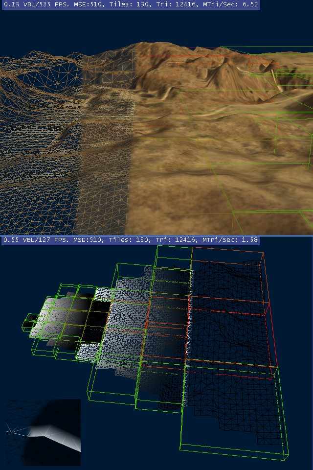
About the pictures:
The top one is from the camera used for the terrain rendering, the bottom
one is an external view of the terrain being rendered from the top camera’s
point of view.
- Each box represents a tile (the bigger the tile is, the lower the LOD).
- For the bottom picture, the shade from black to white represents the LOD
fraction between two levels.
- You can see that fragments of tiles are rendered (instead of the whole
one) on the borders of the frustum to save some rendering.
- The little picture at the bottom left demonstrates what happens when
there’re two tiles of a different LOD stick together. The LOD fraction is
clipped to 0 (for a higher level) or 1 (for a lower level) at the edge to
make the junction perfect.
I Hope you enjoy, you can email me if you have questions.
I may write an article about the technique and release the demo in the
future.
|
|

