 |

Submitted by , posted on 09 February 2002
|
 |

Image Description, by

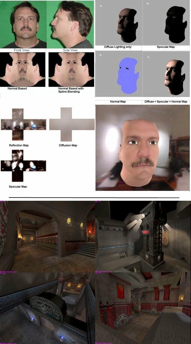
The screenshots in the upper half of the IOTD are part of an article
named "Photo Realistic Faces with Vertex and Pixel Shaders", which will
be published with the source of the necessary tools (diffuse cube map
generator, a texture mapping cylindrical wrapper (MAX Plugin)) and an
example program in the book ShaderX - Vertex and Pixel Shader
Programming Tips & Tricks (Wordware Inc., May 2002). This article shows
step-by-step, how to prepare art in a way, that the result looks
photorealistic and it explains each line in the source code needed to
produce photo realistic faces with the help of vertex and pixel shaders
in real-time.
The top left picture are two photographs from a digital camera that the
technique starts with. It was taken in complete darkness with a Digital
Camera with a flash attached. The green backgound was built from some
fabric purchased at a fabric store and glued onto some poster board.
The two screenshots in the second row of the left half of the IOTD shows
the differences between no spline blending and spline blending. Spline
blending is used by the cylindrical wrapper that is provided with source
as a MAX plugin. The screenshot on the top right shows the various
layers used to make the final image for normal 3D lighting. The bottom
left shows three cube maps that are used in environmental lighting.
The last screenshot in the lower right corner shows a final image when
environmental lighting is used.
Each of these renderings can be done in one pass on a Geforce3 and two
passes on Geforce1 and above. This effect can be achieved in 2 passes
on multitexturing capable hardware by using sphere maps.
The screenshots in the lower half of the IOTD are part of an article
named ""Designing a Vertex Shader-Driven 3D Engine for the Quake III
level and Shader Format", which will be published with the source of a
Quake 3/Return to Castle Wolfenstein level viewer in the book ShaderX -
Vertex and Pixel Shader Programming Tips and Tricks (Wordware Inc. May
2002). This article shows, how to implement a shader system for a
current game engine.
The example program converts the Quake 3/RTCW shader scripts to vertex
shaders while starting up. The author Bart Sekura divided the Quake
3/RTCW shaders into three categories to facilitate the setup code as
well as provide easier and more optimized code paths for rendering:
SHADER_SIMPLE
SHADER_DIFFUSE
SHADER_CUSTOM
The first one is the default Quake III shader that uses base texture and
lightmap texture and constant diffuse. There is no vertex or texture
coordinate deformation and diffuse color is not coming from vertex
stream data. This is by far the majority of shaders, also known as
default shaders, automatically created when there is no explicit script
code. Primarily used for basic world geometry.
The second category is very similar to the above shader type, the
difference being the diffuse color is coming from vertex stream. It also
uses base texture and lightmap. Used primarily for mesh models embedded
in world geometry.
The third category covers all non-standard shaders, which represents
arbitrarily complex shaders, with one or many passes, various vertex and
texture coordinate deformation functions, etc.
Read more on ShaderX at www.shaderx.com.
|
|

