|
Mesh Optimization Via Face Merging by (08 April 1999) |
Return to The Archives |
Introduction
 |
|
Mesh optimizations can vary drastically depending on the needs
of the application. In my application, I needed to optimize a non-BSP tree based mesh.
Although some of these optimizations can be beneficial to a mesh prior to being partitioned, I
doubt than any of these techniques could help to optimize a BSP tree. My meshes are currently generated from the output of the QuArK editor. QuArK is normally used to create maps for id based games, however, by using QuArK to create my meshes, I was able to save large amount of time by not having to create my own editor. All faces in my meshes are convex polygons. This article assumes familiarity with the concept of meshes and some of the problems of creating a mesh with the fewest number of faces. Issue #11 of the Phantom's portal column talks about some of the optimization problems solved in this paper. For more information, and probably better algorithms, see the comp.graphics.algorithms FAQ at http://www.cis.ohio-state.edu/hypertext/faq/usenet/graphics/algorithms-faq/faq.html. It has a section on mesh optimization. |
Optimization Goals
 |
I have three basic goals in my mesh generation. They are in order of importance.
A T-Junction is an intersection of two or more faces in a mesh where the vertex of one face lies on the edge or interior of another face. In many rendering engines, this can cause small cracks between textures due to round off error. (i.e. the EverQuest engine) |
NP Problems and Heuristics
 |
|
(I don't have any formal training in NP problems. Some of my descriptions or classifications could
be incorrect. For a detailed description of NP problems, read "Algorithms, by Charles E. Leiserson.
ISBN 0-262-03141-8) One of the hardest problems with meshes directly results from the algorithms being NP problems. A basic and very inexact description of a NP problem is a problem that can not be solved in a simple deterministic manner. The real description is a problem that can not be solved using polynomial-time algorithms. An example of a deterministic problem is the sorting of a stack of papers by size. To sort the stack, it can be searched for the largest page, and that page is then added to the sorted stack. Repeat this process until all pages have been sorted. The resulting stack is known to be the solution. An example of a non-deterministic problem would be BSP tree generation. With this style of problem, there is no way to choose a first or successive cuts that are guaranteed to provide the best solution. The brute force method of solving this problem is to try every combination to locate the best solution. To avoid having to try every combination of a non-deterministic problem, it is a generally accepted practice to use heuristics to make an educated decision about what would be the best choice for solving any stage of a problem. In other words, through previous observations, the algorithm is designed to programmatically make best guesses. In QBSP, id made the decision that it was their goal to reduce the number of cut faces when creating the BSP tree. So when they needed to make the next cut, they chose to cut along the face that would cut the least number of other faces. However, due to the fact that the BSP tree generation is a non-deterministic algorithm, there is no guarantee that the final solution is the best solution. Now, if anyone is wondering why people don't compute every solution to find the best solution, the number of solutions that would have to be generated to find the best solution for even a trivial map can be extremely huge. |
Optimizing the Mesh, the Right Way and the Wrong way
 |
There are two basic approaches to creating an optimized mesh.
Being a highly regarded programmer in my own mind, I decided to 'Do it right the first time'. The plan was given any cut that is required to the mesh, compute the most optimal cut that will ultimately generate the best mesh. This would have worked great if it wasn't for the reality that non-deterministic problems by nature can not be reliably solved by selecting the best solution for one face, then the best solution for another, and so on and so on. In practice there were many instances where choices made in prior iterations of the algorithm were having a drastic impact on latter cuts. After a few days of little progress, the realization came that the current method of trying to compute the best mesh in a one-pass method was going to require further post processing to optimize away bad cuts. Since post processing was required, then there is little point in trying to make over complicated guesses during the initial cutting of the mesh. The following algorithms were created as needed to optimize the mesh and have some overlapping features. Many might be replaced at a later date with a more generic merging algorithm. Vertex Shifting Optimization When generating a mesh, it is common for the mesh to not be in a contiguous form. An example would be a Quake map. The map contains brushes that intersect with each other. All intersections of the brushes have to be removed and any overlapping faces must also be removed. Consider the problem of Issue #11 (portal column) where a room contains a pillar. 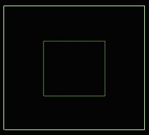 Figure 1 - A room with a pillar After doing basic cuts to make the mesh contiguous, the resulting faces appear as illustrated by figure 2. 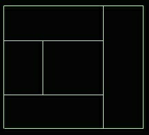 Figure 2 - The room after the initial cuts We can see from the figure that this is a perfectly acceptable division of the room. All faces are convex and part of the floor that is covered by the pillar has been culled from the mesh. However, figure 3 illustrates a better solution for the problem. 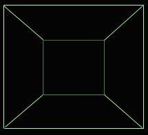 Figure 3 - The best solution There are a few reasons this is a better solution to the problem. The vertex shifting optimization is designed to modify a mesh so that figure 2 becomes figure 3. The first step in vertex shifting is the location of a candidate pair. Using figure 4 as a reference, the criteria for a vertex shift are as follows:
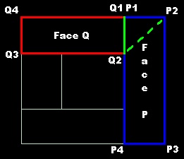 Figure 4 - An example vertex shift If all the criteria are met, in face P, the vertex P1 is replaced with Q2 and in face Q, the vertex Q1 is replace by P2. The dotted line illustrates the new edge for both faces. Two Face Merging Two face merging is the simplest form of face merging. Given two faces that share a common edge, merge the faces into one face as long as the resulting face is still convex. In some cases, the merging can also remove vertices from the mesh. Figure 5 illustrates two examples of two face merges. 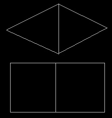 Figure 5 - Two examples of two face merges In the first example, the shared edge is removed leaving a single 4 sided face. All vertices are preserved. In the second example, shared edge is removed along with the vertices. Three to One and Three to Two Face Merging When a more complex object, such as a 10-sided polyhedron cuts a face, it is common to see extra faces being created by the diagonals of the cutting polyhedron. Usually, these faces can be combined into either a single face or repartioned into more than one face. The merging algorithm looks for a triple of faces that share three common edges. Once a triple is found, the following algorithm is used to merge the faces.
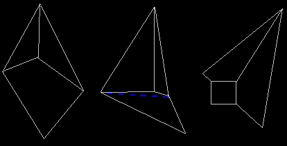 Figure 6 - 3 to 1 face merger, 3 to 2 face merger, and an unmergable face Figure 6 is an example of a three to one and a three to two face merger. In the first case, the perimeter around the faces is convex, thus all three faces can be merged into a single face. In the second example, the perimeter has a bad spot where it is not convex. The dashed blue line shows where the perimeter is divided into two halves thus creating two convex faces. In the final example, this face triple can not be merged into one or two faces. However, it could be repartitioned into three faces that deletes the common vertex. One side benefit of the three face mergers is that it removes a vertex in the mesh. Although the savings would be minimal, removing a vertex does reduce the amount of computations and data storage required to render the mesh. If perimeters with bad spots are still repartitioned without the checks in step 3, then there is a chance more faces will be created than will be culled. However, any common interior vertex will be removed. Since the resulting faces would be simpler faces, they might now be mergable with other faces in the mesh. Also, in hindsight, the restriction that the three faces must share three common edges is not required. After changing the code to require only two contiguous shared edges, the algorithm merged another 1% of the mesh. More complex meshes than my test mesh should show greater optimizations. Ultimately, I am going to pursue all of these changes, but only as part of a final N face merging algorithm. |
N Face Merging
 |
| There should be little reason why the three face merging algorithm can not be expanded to include N faces. This algorithm would collect the perimeter of mergable faces as long as the faces were continuous. (i.e. no donut holes in the middle of the faces.) After the perimeter is generated, any bad spots could be removed using the same technique used in the three to two face merger. The N face merging could replace both the two face and three face merging algorithms. |
|
|