 |

Submitted by , posted on 08 November 2004
|
 |

Image Description, by

The poem, it was the poem... and the cheddar. It left me no choice but to also submit an IOTD, so here I am...
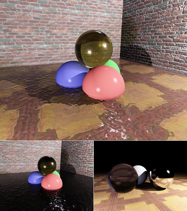
Let's see... more than three years have passed since my previous Image Of The Day, too long to remember! A lot of things have happened, too... except working on said raytracer. Then Jacco Bikker (aka The Phantom) started his raytracing column - an excellent opportunity to get back on track myself, I thought. So, I wrote a little tutorial and started coding again. The result is displayed above (pure raytracing, no global illumination yet). What you see are reflective/refractive spheres, walls and floor. Particularly noteworthy are the transparent spheres and the bumpmapped water... Our three gentlemen, Mr. Snell, Fresnel and Beer explain what's so special about them:
Mr. Snell: "Both the sphere and the water are not only transparent, but also have an index of refraction (n = 1.5 and n = 1.33 respectively). Thus, the rays of light must be refracted by my law." That's done here (well, at least for primary rays, shadow rays don't obey this). Observe the lens effect in the sphere and the distorted floor through the water; this is what my tutorial "Reflections and Refraction in Raytracing" is about.
Mr. Fresnel: "In most ray tracers, reflectance and transmittance (reflection and transmission coefficients) are given by hand. And maybe that works fine for you, but I don't like it because it's not natural. Here I have equations that calculate the reflectance and transmittance on interfaces between two materials with different indices of refraction, and for every angle of incidence. You should use them." And that's exactly what I've done for the glass sphere and the water. Well, not really, because I didn't like the idea of simulating polarised light, so I cheated with a simplified equation proposed by Schlick (if you like French, you'll find it as equation 3.24 in his Ph.D thesis). Anyway, notice the reflections on the water and on the sphere.
Mr. Beer: "In many ray tracers, the colour of transparent objects is totally determined by the surface material. In case of transparent solid, rays are tinted twice (on incident and exitant transmission). Of course, that's not correct: It's not the *surface* that determines the sphere's color, but the material *inside* the sphere. This is also true for water: it's not the water's surface that tints the light, but the water itself. You should alter the light intensity based on the distance traveled through the medium. That's only obvious: if you travel through a thick plate of glass, light will be tinted more than it would through a thin plate." So, I've implemented that as well: if light travels through a medium, its intensity is affected by Beer's law. The surface of a material can still affect transmitted light (e.g. for a coloured coat layer), but in the above scene this surface colour is set to white (this is also explained in part 3 of Jacco's column).
To illustrate the effect of Beer's law, I rendered the same scene with more dense glass and water (higher extinction rate in the exponential decay term). In particular, notice how the three coloured spheres quickly disappear in the water, and how you can see the reflections better in this rendering. That's not because the sphere and the water have become more reflective, but simply because the background on which they're displayed has become darker.
So, what's next? Global Illumination I suppose... I've been hacking a photon mapper today, but it's too early to show any results yet... but that's only an excuse to post an IOTD later :)
Anyway, that's it for today. Happy coding, folks.
Bram de Greve
P.S. Oh, I almost forgot: I've spotted an error in my tutorial, can you find it too? :) I'll send the corrected version to flipCode later, with a special mention for anyone who finds the mistake.
P.P.S. Thanks Thomas ;)
|
|

