|
ROAM Implementation Optimizations by (24 July 2001) |
Return to The Archives |
Introduction
 |
|
The terrain is an essential part of an outdoor game. Bryan Turner has examined some of the most widely used hardware accelerated landscape algorithms in an article, which you can find at Gamasutra.com [1]. Hardware accelerators have evolved since. I have found myself asking the question "Does it make sense to use a dynamic view dependent level of detail (VLOD) terrain algorithm with modern 3D accelerators?" This article does not answer this question but hopefully supplies you with enough information to find the answer yourself. |
|
Hardware Accelerator Optimizations
|
There are several optimizations (DirectX) we can make to improve the performance of a 3D hardware accelerator:
|
|
Dynamic vs. Static Landscape Algorithms?
|
|
If it does not make sense to use a view dependent level of detail algorithm with the modern 3D accelerators, what can we use instead? What do we mean by the term "static algorithm"? Static vertex and index buffers are those that are written once and then used many times. Running a (view independent) LOD algorithm on a height map and storing the produced data in "static" vertex and index buffers allows the DirectX run-time to store the buffer content in video-memory. Then you simply make the fastest DrawPrimitive calls ever. Sometimes referred to as a "brute force" algorithm. "Static algorithm" implies that: If the landscape itself is not changing, i.e. is not dynamic, a "brute force" algorithm will probably be the best choice. Richard Huddy of nVidia recommends the use of "brute force" with current hardware accelerators. There are still some improvements regarding the performance of the "brute force" algorithm that can be made. We can use some high level spatial sorting to exclude large chunks of terrain (whole buffers) which are not visible at that particular moment and improve the z-order. What do we mean by the term "dynamic algorithm"? A "dynamic algorithm" is one that uses a VLOD algorithm to process the terrain mesh and supply the data to the GPU through "dynamic" vertex and index buffers. Features of "dynamic" algorithms: There are lots of VLOD terrain algorithms out there. So what is the answer then? You should decide which type of algorithm would be suitable for your needs. I have implemented both types in the demo, so you can experiment and decide for yourself. At this point, I am going to introduce the optimizations I have used for VLOD (ROAM) in order to get the fastest performance possible. If you are not familiar with the ROAM algorithm, Bryan Turner�s article will be an excellent starting point. I recommend you read it, as my paper does not cover ROAM basics and follows closely with his article�s terminology and implementation. |
|
Why Indexing?
|
|
The ROAM algorithm tessellates rapidly and produces a lot of vertices. There are optimizations based on triangle fans or strips. However, unless we could make a continuos buffer of strips or fans this would have resulted in numerous DrawPrimitive calls, i.e. reduce batching. If we take a look at DrawPrimitive calls performance [2], it is noticeable that the index ones are faster. The GPU cache is utilized only with indices, though the triangle lists are usually about 25% slower than strips. Due to the specifics of the algorithm [1] we are using indexed triangle lists, which results in a single vertex/index buffer per texture. We sacrifice strips in the name of batching. |
|
Delivering Buffers
|
| Dynamic buffers are usually created in the AGP memory [2], which is expensive to read and cheap to write for the CPU, though random (not sequential) write operations can also decrease performance. For this reason it is sometimes useful to keep a copy of the buffer in the main memory, update this copy, and then overwrite the whole buffer. |
|
How To Index With ROAM?
|
|
Now let us take a look at the ROAM algorithm. In order to take advantage of the render recursion [1], we add three more parameters to the render function, namely the indices of the left, right and apex point (passed by address). RecurseRender(TriangleTreeNode *tri, int lx, int ly, int rx, int ry, int ax, int ay, WORD *il, WORD *ir, WORD *ia); When a leaf is reached, we check whether the three indices are real (we have assigned the value of 0xffff for a dummy index). If one or more indices are not already created, we add their vertices to the vertex buffer. The position in the vertex buffer is then used as an index value, and the three indices are output to the index stream (triangle list). In this way, we have assigned indices to the points effectively reusing the vertices in the vertex buffer. The following example shows the recursion steps and indices are assigned. 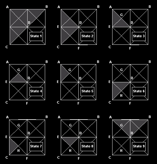 State 1: We start with the left base triangle (CBA) of a small patch (we will be specifying the triangles by their left, right and apex point for clarity). State 2: The recursion takes us down to the left child (ACD) passing the addresses of A,C and D down. State 3: This process in State 2 is repeated (DAE), with the addresses of D,A and E passed. State 4: Finally we get to the leaf EDG, we check the indices which currently are E=0xffff, D=0xffff and G=0xffff and create new vertex info for these vertices, assigning them real indices, 1, 2 and 3 respectively. These are output to the index buffer. State 5: We go to the other leaf (tree traversal) and we arrive at AEG. These indices are checked at this point. Apex A has an index value of 0xffff, whilst apexes E and G have values of 1 and 3 respectively from the State 4 operation. In this case, we only create a vertex for A, assigning it the next available index value i.e. 4, and then output the three indices into the index buffer (remember, we have just reused two indices). State 6: As we have finished with the leaves in this branch, we move up the tree and proceed with the right branch triangle CDE. State 7: We move down to ECH and find that this is a leaf. When checking for the indices, we find C and H have dummy values, so we need to create some (5 and 6 for C and H). Apex E is already set to 1 (as defined in State 4). The indices are output. State 8: The right leaf here is DEH. In this case, the indices have already been created, so we can reuse them (they come at order 2,1,6). State 9: We move up the tree due to recursion exit and continue with the other child of the base left triangle of the patch. At the current moment we have 6 vertices and 12 indices. We can explore this example from a nVidia GPU cache point of view. There are two types of GPU cache in the GeForce family - memory and vertex. Regarding the memory cache, the only optimization we can make is to fit our FVF (Flexible Vertex Format [3]) into 32 bytes, as this is the size of the cache line. This is not generally correct, but might apply to this case because we are obliged to use random access patterns (This is stated as a significant weakness of the Roam algorithm). The vertex cache (a.k.a. cache of post-transform and light data) is a FIFO cache and consists of 10 vertices. Here is our index buffer (4 triangles): 1,2,3, 1,3,4, 1,5,6, 2,1,6 First triangle - all vertices are new. Second triangle - one new vertex for the cache (equal to the strip version - with strips we have a new vertex every triangle) Third triangle - two new vertices for the cache (one vertex less than the strip version) Fourth triangle - no new vertices for the cache (better than the strip version, with 1) Our example equaled the strip version, but this is the best case. On average we will suffer 20% less performance, however it will be far faster than small chunks of strips. The average strip or fan length with ROAM algorithm is 5-6 triangles [6]. |
|
To The Code
|
Here is the initial code for the tree traversal call:
This is a good start, but if we try this code we will find that there are still vertices duplicated in the vertex buffer. So what went wrong? Imagine there is a diamond (in [1], this term refers to two triangles that share their base side - in our example, EDG and DEH are in diamond). In this case, the code proceeds with the children recursively, but after their recursive functions return and our function exits, our center point index goes out of scope and our index is lost. At the time the base neighbor has to handle the rendering process it will create one more vertex for the same point. To correct this problem, we add an "index" data member in the TriangleTreeNode. Now when we have to traverse the children of a node, we pass them the address of the current node "index" member and then update the base neighbor index, if any.
|
|
Indexing & Textures
|
|
Most of the time we will want more than one texture for our landscape. We can still make a single vertex buffer and output different chunks of indices, while changing the texture. Now, let us take it from the beginning. We have different textures for one landscape. In addition, we have different sets of textures for the same landscape (perhaps multiple texture blending). We can encapsulate a set of textures in a "render state batch" which I will refer to such batches with the word "texture" for clarity. |
|
Multiple Index Buffers For A Single Vertex Buffer
|
| We can use a different index buffer for each texture set, thus it is possible to write concurrently in all the index buffers, and then output each index buffer changing the texture sets once for each index buffer. We keep the same vertex buffer - switching vertex buffers can be costly. |
|
Patch Aligned Textures
|
|
Aligning textures to the patches will result in a mix-up of texture coordinates. Remember that we have already found an index for a vertex in one patch. Having a base diamond neighbor in another patch means that the vertex will be reused. The texture coordinates of the vertex in the other patch are most probably will be different so they can't be reused. A solution to this problem is to prevent indices to cross patch boundaries. We will take another approach as it allows to solve more elegantly (not fully) another problem. Here is my tricky idea about the texture coordinates. If we mirror our textures we can successfully re-use a vertex texture coordinate for both textures meeting at a vertex (see the diagram below). 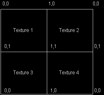 Some texture filtering issues arise, which result in visible texture boundaries. For example, if you use "linear" filtering in DirectX, it is computed from "weighted average of a 2�2 area of texels surrounding�" [3]. If we are at the border of the texture this computation is not exactly what we want. A partial solution is to set the addressing of the texture to mirror instead of wrap, which makes this artifact less noticeable. The demo uses mirrored textures. |
|
Dynamic Issues
|
|
Tree Node Merging It would be a waste of time and computational resources to tessellate the landscape each time, when we can just update it according the FOV (field of view) and the position of the camera. A lot of people will claim that it is very cheap to rebuild the tree and there is no need to bother updating it. These people are probably right, but we have something valuable in our tree we do not want to lose - the indices. Memory management for nodes I came up with a trivial method [4,7] for memory management for the nodes, which efficiently enables merging and still manages to keep the efficiency of pre-allocated memory as well as the ability to quickly reset the pool for new tessellation. We have a static pool, which initially allocates the memory, and a dynamic one, which is a linked list (we can use one of our pointers in the TriangleNode to point to the next "free" one). New node: if the dynamic pool is empty we get a new node from the static pool, otherwise the node is acquired from the dynamic one. Deleting: we just add it to the dynamic pool (linked list - managing couple of pointers). Resetting: just reset the dynamic pool (sets the "head" pointer to NULL) and the static one (node counter to 0) and we are done. Merging Split/Merge priority queues can be implemented here which will introduce a performance improvement. However, to keep the code clear we use the same recursive tessellate function to update the binary tree, merging when variance is low. Our FOV occlusion can be integrated there too. We can use variance computation deferral. Depending on the size of the variance (and the speed of the camera), we calculate number of frames to delay the computation of the variance for the current node. There are two functions which concern merging. Merge, which handles a node merging and MergeDown, which recurs down the tree until reaching some nodes with leaves to be merged. MergeDown relies on the fact that if the merging decision was taken up in the structure then it applies for all descendants. An important thing for the Merge function is to keep the connectivity information in neighbor nodes. Failure to do so can result in many sleepless nights chasing terrible bugs (speaking from personal experience). If the current node is skipped by occlusion then we run a MergeDown function on it. However, when split/merge operations appear in the field of view it is good idea to implement some geo-morphing in order to prevent the popping. If merging (or splitting!!??) occurs due to a node being outside the view frustum, there is no need to geo-morph. After all we can�t see it (or can we?). In fact, when we have the tree built it is just a question of update. We usually do not rebuild the tree until the free nodes count goes under a certain limit. The ROAM algoritm tessellates quite rapidly and merges rapidly as well. We can alter our limit variance to decrease detail level and thus maintain free nodes count and frame rate too. Generally it is a good idea to rebuild (re-tessellate) the tree if there is some major change of the FOV (camera "teleportation" or sudden and fast camera rotation), although this is not done in the demo. Index merging (updating) The first time we traverse the tree for rendering we create our initial vertex buffer and our index buffers (each per texture). When updating the tree, new vertices are introduced due to split operations, whilst other vertices are discarded (merge). We can just add the new vertices with D3DLOCK_NOOVERWRITE [3] lock of the vertex buffer. How is this achieved? We traverse the updated tree with our trivial render function and build the index buffers, as there is index information in the nodes which is still valid. Discarded vertices are not referred to and new vertices are created. When we reach the limit of vertices in the vertex buffer, we reset and start again (all index information in the trees nodes is reset, as it is invalid now). There is a place for one more enhancement here. During the tessellation step a flag can be used to indicate if there have been any changes in the patch. If the flag shows there are no changes, we can immediately invoke the DrawIndexPrimitive call for the patch. On the other hand, if the patch has been changed, the recursive render function has to be run. We lock the vertex buffer with D3DLOCK_NOOVERWRITE [3], add the new vertices and construct the index buffer. The GPU will render our "untouched" primitives while we are locking and writing our complement to the vertex buffer. Field of View We can use the view frustum culling during tessellation to reduce the node count, as well as during rendering process to reduce primitive count. We have used 6 planes view frustum in world space. We get the view and projection matrices and compute the 6 planes and then check the geometry. The easiest thing we can do is to compute the positions of the three points of the triangle and check them against the frustum planes. This would check whether this triangle is in, out or intersects the view frustum. If the triangle is reported out of the frustum, then we skip its children, although it can be possible that its children due to their different height (y component) are actually in the frustum. For this eventuality, we have to occlude against bounding volume which encompasses all the children. Diamond circle (cylinder culling) Let us consider an isosceles orthogonal triangle. The center of the circumference, which has the tree apexes of the triangle, is the middle point of its hypotenuse (remembering that the height of the triangle is a � of its hypotenuse). Although the circumference contains the three apexes of the triangle, it also encloses a wide area of space, which introduces a large error in the frustum check. This is an error we can live with, and moreover, it is one we can actually take advantage of to some extent. We should consider that the hypotenuse of a triangle is a hypotenuse of its diamond base neighbor, and once the visibility information is computed for the current triangle this will give us the information for the base diamond neighbor. In the ideal case this will save half of our computational work. The radius (1/2 of the hypotenuse) can be computed recursively. All triangles are right-angle isosceles - children are similar triangles to their parents. In fact, the factor of similarity between children and parent triangles is sqrt(2)/2. The hypotenuse of the initial triangle is a*sqrt(2)/2, considering a is the side of the patch. These values can be pre-computed and stored in a small array, as they depend only on the recursion depth. These triangles are right isosceles only in 2D. When we add the third component, namely the height, they will be far away from this definition, although their projections on the ground plane will be right isosceles. In this case, a cylinder can be used to check the visibility information. We already know the radius (1/2 of the hypotenuse) and the height of the cylinder is the difference between the highest and the lowest point in the triangle. We can pre-compute the highest and lowest point for the triangle (we should choose a merged minimum/maximum height in order to fit the volumes of both triangles in the base diamond). We use a single height value as this will save some memory. Picture 3 shows two triangles (base neighbors) and their bounding volume. Projections on the ground plane are right isosceles triangles (A�B�C� and A�B�D�) 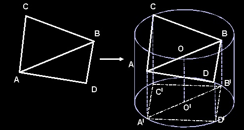 Then we end up with a cylinder to frustum check. As long as height of our cylinder is aligned to the "up" vector (0,1,0), some of the computations can be skipped while checking with the view frustum. We use the general idea of altering the view-planes distance with the radius of the cylinder, according to the orientation of the cylinder to the planes [5]. Taking advantage of the fact that all our cylinders will be "up" orientated, we can pre-compute the information for six frustum planes and reuse it. We can further improve the 6 plane occlusion. If a volume is found not intersecting a plane, then the children volumes need not to be tested with that particular plane again. We reuse our occlusion BYTE flag that we are passing down the recursion. There are six bits - one each per plane. If the value of a bit is one, then checks with that plane are made. If the value is zero, then the checks are skipped. If due to the checks the plane was found not be intersecting the volume then its bit is reset to zero. This little trick will make the cylinder frustum check (plus the visibility sharing for the base neighbor) take less than 15% of the time (VTune report). Finally we can do something more to our landscape class. We can use a more tricky data structure of our patches than just a simple grid - a quadtree. This will allow us to do quick and effective occlusion. Do not forget that when checking whether a quad is in or out of the frustum, that the nodes are not simply 2D squares but also have a third component - height. Cylinders can be reused, as they have already been prepared for an "up" orientated check. Back-faces Another option is to switch the back-face culling on and output our indices in the appropriate order. This is done without any effort and is quite trivial, but should be mentioned. |
|
Additional Optimizations
|
|
Spatial sorting Once built (tessellated), our triangle binary tree can be used for "back to front" or "front to back" sorting of the triangles, which can increase performance or help us with special effects. Before making recursive calls, we only need to check which child is closer to the camera and then use the appropriate call order. Back to front: if you do not have access to a Z buffer then this is your best option as near triangles will overwrite the far triangles (Also known as 'The painter's algorithm'). Front to back: if you do use a Z buffer many hardware accelerators will gain performance of such order. Although this point is valid, it is more important to maintain low texture changes and improve batching, than gain performance from helping the Z buffer do its job. Note that the same sorting can be applied for the quadtree of patches in our landscape class. This will be better idea as the sorting is done at higher level. Reusable map patches Some games use map patches to build enormous worlds. In these cases, the same terrain patch also has the same variance heaps (implicit binary trees). The variance heaps can be moved into the map class, thus one can use several patches with the same map chunk and still keep a single pair of variance heaps. Geo-morphing We have mentioned before on several occasions this "geo-morphing". It is simply vertex morphing when you split (or merge) a triangle in order to avoid sudden popping. If our time T varies from 0.0 to 1.0 and we have to morph from Hc (estimated vertex) to (Hr - real vertex) the output vertex is: VetexH = Hc + (Hr - Hc)*T How does this fit with our indices? In order to visualize this morphing, we can add the vertex to the vertex buffer and redirect all the indices that point to the old one to point to the new one. There are actually four triangles affected by this operation (the leaves of the two triangles that are merged), so we just need to update the indices of the two parent triangles and reconstruct the index buffer for this patch. |
|
Results
|
|
Having implemented most of the improvements described we have noticed (using a profiler) that the main overhead is in the recursive tessellation function. The problem is that usually when we proceed with the children nodes, the pointers are mostly cache misses as the tree is not a sequential data structure. Currently most games are still CPU limited. An algorithm, which is very CPU heavy (like ROAM for example) is unlikely to be a good choice for a game. The late break hardware is capable of drawing hundreds of millions textured triangles per second and the CPU load limits this number to a million or so. We can see that the "static" version though not optimized is much faster than the dynamic one. |
|
The Demo
|
|
There is a demo with source that accompanies the article. The code is fully commented. Download it here (930k) The folder "textures" contains the texture generator. It will generate textures (mirrored) for each patch (64x64). The demo was built and tested with DirectX 8.0 SDK. In the demo source code the static version is not quite optimized. Index buffers should be static and some patch occlusion can be done while brute forcing. F1 - toggles from static to dynamic algorithm F4 - toggle fullscreen |
|
Special Thanks To...
|
|
Justin Mitchell for helping with the linguistic problems in the article. Vladimir Koylazov for all the valuable pieces of advice and support. (http://www.chaosgroup.com/Vlado) Klaus Hartmann for helping me with the texture synthesis. Richard Huddy for the valuable comments and ideas he gave me. |
|
Bibliography
|
|
[1] Turner, Bryan; Real-Time Dynamic Level of Detail Terrain Rendering with ROAM http://www.gamasutra.com/features/20000403/turner_01.htm. [2] Huddy, Richard; Numerous presetations at nVidia developer relations site concerning performance with DirectX. http://partners.nvidia.com/Marketing/Developer/DevRel.nsf/TechnicalPresentationsD3D?OpenView [3] The Microsoft DirectX 8 SDK Documentation [4] Dov Bulka, David Mayhew; Efficient C++: Performance Programming Techniques [5] DeLoura, Mark; Lengyel, Eric; Game Programming Gems A Fast Cylinder-Frustum Intersection Test [6] Mark Duchaineau, LLNL, Murray Wolinsky, LANL, David E. Sigeti, LANL, Mark C. Miller, LLNL, Charles Aldrich, LANL, Mark B. Mineev-Weinstein; ROAMing Terrain: Real-time Optimally Adapting Meshes http://www.llnl.gov/graphics/ROAM/roam.pdf [7] Meyers, Scott; Effective C++: 50 Specific Ways to Improve Your Programs and Design |
|
|