|
Merging Polygons And Sub-Pixel Gaps Question submitted by (27 March 2001)  |
Return to The Archives |
 |
 |
||
|
My BSP/PVS compiler does CSG on all brushes before BSP-ing to remove all the
"illegal geometry" (caused by intersecting and touching brushes). This
causes a LOT of splits. It doubles the polycount. When I look at the
wireframe shots I can see a lot of faces can be merged.
How do I know when 2 faces are convex forming and more important: how do I
merge them? My second problem is: sub-pixel gaps caused by T-junctions. How can I find and correct those gaps? I thought of the following but for some reason it doesn't work:
Any help would be appreciated, Dennis Meffert |
|||
 |
 |
 |
 |
||
|
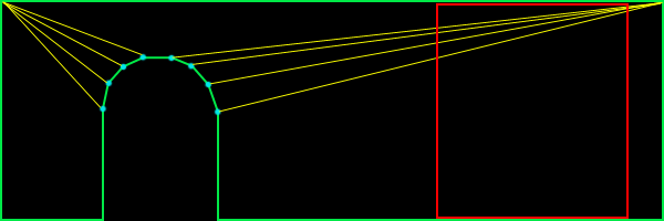
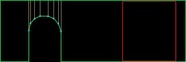
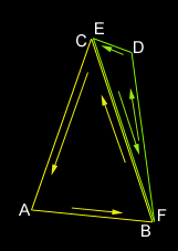
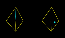
Hi Dennis, Two excellent questions! The first question, in particular, I've been waiting for somebody to ask (I even hinted around about it in a previous response.) The second question is actually the last phase to the solution for the first. Confused? :) To clarify your first question, what you're really asking is how to automatically "optimize" a set of polygons. The answer to this is non-trivial. Fortunately, it's on my list of "documents to write when time allows." Unfortunately, time doesn't look very forgiving for me in the near future, so I'll run through the important points here, and skip the details. It's been a long time since I had to do this (before my TRI days), so I beg your pardon in advance for anything I may overlook. DEFINE THE GOAL Don't get lost in your problem of "merging polygons" - that's only a part of the problem. I'm going to attack it in terms of optimization. This is not to be confused with LOD reduction. We want to keep the exact same topography for the scene, but we just want to do it in fewer polygons. When I originally set out to do this, my goal was to find "the most optimal set of convex n-gons from a set of polygons." Let's pull that statement apart. I realize this sounds over-dramatic, but please bear with me. The three parts are "most optimal set" and "convex n-gons" and "set of polygons". I'll cover the last two first, because they're quickest. Obviously, "convex n-gons" means just what it says. I chose to go with them because, at the time, it was best (and I'm still convinced that they're good to go for the current state of things.) When I say "set of polygons", I mean set of any kind of polygon. I didn't actually intend on handling any kind of input polygon, but as it turns out the technique allows for complex input polygons. Now about that "most optimal set" bit. What does this mean, and to whom? No I'm not trying to act like a psychologist, I really mean it. For example, I might optimize the set into the fewest possible polygons, which would speed up my pipeline. However, this doesn't necessarily always get you the best frame rate.  In figure 1,we see a standard wall with an archway. This shape is represented with 9 polygons (12 triangles.) Take special notice of the red square. This is the portion of the surface that is within the frustum (or not occluded by something.) In this case, I count a minimum of 5 polygons (6 triangles) inside the frustum.  In figure 2, we see a much different approach. This shape is also represented by 9 polygons, but 18 triangles (as opposed to 12 triangles in figure 1.) However, there is only one polygon (2 triangles) in the frustum. Obviously, it depends on what is being viewed as to whether or not there is a savings in going with the way figure 2 has things laid out, but in practice, I found this way to be better than the standard solution. This is especially true for highly occluded scenes. OVERVIEW In short, you have to completely rebuild your scene. Anything less would simply be an incomplete solution. The advantage to doing so is that your scene gets completely optimized. The steps are as follows: 1. Completely rebuild the scene into complex polygons 2. Split the whole scene up using whichever "best fit" solution you want 3. Remove t-junctions STEP 1: HOMOGENIZE Step 1 is really the most involved. Notice that step 1 uses complex polygons, not convex polygons. This means that polygons can be concave and can also have holes. The only limitation I place on this, is that they cannot have crossing edges. Also, note that they will need to be correct complex polygons (i.e. the winding order of the vertices in the holes go opposite to the winding order of the exterior vertices.) This may sound difficult, but its not too bad, really, if you're careful. Step one actually starts by removing t-junctions. But since I'm going to cover them in step 3, I'll not waste the space here. Just know that the whole process starts and ends with t-junction removal. Start by choosing a polygon (it doesn't matter which.) Put the vertices into an ordered list. If your input polygon is a triangle, you'll have three vertices in your list: A->B->C. Remember, this list represents vertices, so it should be treated like a circular queue (i.e. A -> B -> C -> A ...) Now throw that polygon away; consider it "processed." We're going to be building on this list of vertices, adding vertices to it until we have a complete polygon and we can find no more polygons that share edges with it. In order for a polygon to be considered for merging, we need to make sure that the polygons have the same properties. For example, the two polygons must be coplanar. They must have the same material applied to them, etc. So let's start merging. Find a polygon that shares an edge with our vertex list (ABC.) Remember, sharing edges go the opposite direction. You would naturally think that two polygons with the same winding order would be shared in the order they appear. For example, polygon ABC and polygon DEF might share BC with EF. In reality, it's BC shared with FE. Here's an example of two polygons sharing an edge:  When you find a polygon that shares an edge (and shares the same surface properties), it's time to merge them. Simply delete the two vertices from polygon DEF that were shared with the vertex list. This would delete E and F, leaving us with D. If your input set is more than triangles, you will have more vertices left over. Insert the remaining vertices (in this case, just D) into the list between the two vertices that were shared (in this case, between B and C.) Now throw away the polygon that was just merged and consider it "processed." Our new list now is A->B->D->C. Continue this process until you find no more shared edges. At that point, you'll have your first (potentially complex) polygon. Pick another polygon (any polygon will do) and start over. Lather, rinse, repeat. Before I go on to step 2, let me briefly point out a few common gotchas (at least, the ones I can remember.) First, if your input data has a lot of garbage in it (as was most of the archaic 3DS file stuff I was working with), you might run into some degenerate polygons (i.e. polygons that are infinitely thin) or polygons that are multiply defined (i.e. three vertices used to define two identical polygons with the same normal.) These can really trip you up, so be careful, and use lots of ASSERTS. STEP 2: SPLIT IT UP At this point, you have no more polygons; they've all been merged into a bunch of vertex lists (which, in effect are still polygons, but lets think of them as lists for now.) How we proceed from here, depends on which best fit solution we want to go with. I'm going to stick to what I know, Monty, and go with what's behind figure #2. After reciting a short prayer to the deity of computational geometry, we're ready to begin (no, that doesn't actually help, but the chicks dig it. =) We're going to be working with one list at a time, splitting them each up into usable polygons. For this, we'll need a concavity test and an area calculation that works with complex polygons. You'll find them in the appendices (?!) at the end of this document. We want to split up these polygons until we get a "best set" of convex n-gons. If you want triangles in the end, then you'll have to take that last step on your own (there are plenty of references out there that cover this.) If the list of vertices defines a convex polygon, consider it finished. Otherwise, we'll need to split it up. This process begins by selecting an edge (two consecutive entries in the list) from the list of vertices. We'll attempt to split the polygon by that edge. Here's an example:  In this example, we have two possible splits. Notice that if we tried to split by any other edge, the polygon would remain whole. We'll be testing each possible edge for a split. We don't want to stop when we find one that works; remember, we want a "best fit" solution. What we're looking for is the split that results in the single, largest, valid fragment. Looking at figure four, we see two potential splits. On the left, we find a split that results in a very small fragment and a larger fragment; we'll keep track of the area of the larger fragment. On the right, we see another split. If we calculate the areas, we'll find that the area of the larger fragment is not as big as the larger area of the previous split. I sure hope that's not too confusing. Once we've tried all possible splits for this polygon, we go back to the one that resulted in the largest fragment. It is now safe to throw away our current list of vertices and replace it by the two smaller fragments. Next, go back up a few paragraphs to the point where I said, "If the list of vertices defines a convex polygon..." and (you know the drill) - lather, rinse, repeat. So, how do you split a complex polygon? This actually goes beyond the scope of this document, but there are plenty of references on the net. Paul Bourke's home page (http://www.swin.edu.au/astronomy/pbourke/) is a good place to start. STEP 3: REMOVE T-JUNCTIONS If you've made it this far, you've probably noticed that we've completely munged our world geometry (twice!) in order to completely reconstruct it. At this point, we've got a terribly optimized database, but filled with a lot of t-junctions, because of the way we've split up the polygons. No problem, step 3 to the rescue! I've done t-junction removal two ways in the past. Take a peek at figure 5:  On the left, we have the standard "split it up" and on the right, we have the "slide". These aren't dance moves, they're just lame names I come up with for stuff when I'm bored. Splitting it up is really straight forward, but ends up with an extra polygon. Occasionally, however, you can slide a vertex to collapse two polygons into one. It's usually a good idea to do this whenever possible, because in this case, fewer polygons is always the best. Note that you can only slide a vertex when the two polygons being collapsed are coplanar (and share the same surface properties, don't forget!) We must first detect when a vertex is the source of a t-junction. Looking closely at either half of figure 5, notice how the two polygons share two vertices, but not an edge. This is a great trivial rejection test. If you don't find this to be the case, then you're guaranteed not to have a t-junction with these two polygons. Otherwise, we need to test for a t-junction. Testing for a t-junction involves ignoring all vertices that are shared and testing the remaining vertices to see if they lie on the edge defined by the opposite polygon. How do you determine if a point lies on the edge? Here's a simple way (there are more efficient solutions, but this one, at least, is pretty simple): Calculate the vector of the edge and then calculate the vector from one point on the edge to the vertex being tested. Normalize them and then take the absolute value of their dot products. If that value is within a tolerance to 1.0, then the vertex lies on the line defined by the edge. The only thing left to do, is to determine if the vertex is between both edge points. You can do this, by creating two vectors (one from each endpoint of the edge, pointing at the vertex) and see if they point at one another. For those purists out there, you'll find a more efficient solution on Paul Bourke's page. Once we determine that there is, in fact, a t-junction, we can split the opposing polygon. This is as simple as inserting the source t-junction vertex into the opposing polygon (between the two edge vertices) and replacing that polygon with the two pieces. This is all just simple vertex manipulation, but what about sliding? Sliding involves a little bit of extra work. As a matter of fact, it's a lot trickier than I expected to explain, and since I'm already on page four or five of this response, I'm going to totally bail on this one and leave it up as an exercise to the reader. :) Actually, if somebody is interested, send in another question and I'll cover it. That pretty much covers the topic, but we've still got some loose ends to clean up... APPENDIX A: CONCAVITY TEST The way I've always done concavity testing was quite simple. I would build a plane out of each edge. You can do this, by taking the cross product of the polygon's normal and the edge-vector. This gives you an "edge-plane" normal. An edge plane is that plane, which is defined by the two endpoints of the edge, and perpendicular to the polygon. If you were to attempt to bisect the polygon on all of its edge planes, what would happen? If the polygon was convex, nothing would happen. So we test for this. The quick and dirty answer is to simply visit each edge-plane and test each vertex to make sure they're all on the same side. If not, then the polygon is not convex. APPENDIX B: AREA CALCULATION FOR COMPLEX POLYGONS We need an area routine that works for complex polygons. I found a fantastic little ditty in CGP&P that worked for 2D polygons, and extended that to 3D. It's fast, and very accurate:
CLOSING I should warn you that this is not trivial code to write. This is the kind of code that can be pretty hairy without good debugging tools and techniques. I remember actually writing a mini-debugger for this that would render the polygons (perpendicular to their plane) to a series of image files, so I could investigate what was happening along each step of the process. When I eventually tackle this again (and I will -- it's already been scheduled), I'll be sure to publish the source code to it. In my experience, I've seen this algorithm (or something very similar to it, depending on how true my recollection really is) generate, on average, greater than 50% polygon reduction, with similar improvements to my frame rates. Personally, I would consider that well worth the effort.  Response provided by Paul Nettle |
|||
 |
 |
|
This article was originally an entry in flipCode's Ask Midnight, a Question and Answer column with Paul Nettle that's no longer active. |