|
Dirtypunk's Column - Issue 03 - Visibility Theory by (05 April 2000) |
Return to The Archives |
Introduction
 |
|
Well, its time for another instalment in my latest manifestation in active tomfoolery and general beating of the shared common psyche of the general game development into something resembling my rather twisted shell of a self. Or not... Anyway, this week, I decided to start on one of my favourite (and this is known to many people) topics, and that is visibility theory. Some of this may not actually seem useful, until you are developing a vis system on your own and need to make some decisions on what you are doing. Anyway - with out further useless boondoggling… |
|
What In The Name Of Umpa Lumpas Is Visible Surface Determination Useful For?
|
| Here we have a title which may as well be translated to "Why do you find this topic interesting, and why are you writing on it?" The obvious answer is that I am being self-indulgent. That I will not deny. But, further forward, this is a topic that provides the answers to a great many problems of 3d computing. These include performance issues with interactive and non-interactive rendering, static and dynamic shadow computation and global energy transfer including lighting, sound and if you really want to, measuring it heat transfers. |
|
Establishing Some Definitions
|
|
Well, here we must go forwards and make some definitions of things elementary to what will be discussed below. The first thing that must be introduced is that visibility is defined in terms of lines. Normally, maximal free segments. This is basic, a line which stabs (intersects/touches) two polygons/points/edges without stabbing anything in between means that the two things in question are visible to each other. Pretty simple. From this we can extract the concept of visibility events. In singularity theory these are what are known as Catastrophes, and often are also referred to as Discontinues (eg Discontinuity meshing which gets more accurate results in radiosity, by subdividing patches based on visibility events, instead of dividing uniformly). Visibility events are where a change of visibility occurs. For example, where does an occluder (or set of occluders) stop occluding an occludee? In 2d, a line tangent between two objects defines all these events. However, in 3d a line is not a hyper-plane, as in 2D (if we got on to super string theory etc, we could go on about a line being a brane of 3d), meaning that a line does not divide the dimension in to two spaces. This means that we can not use lines as a bound to a 3d space. Where as visibility in 2D we can, as a set of 3 non-parallel lines form a bounded area. In 3D, there are a few types of visibility events such as VV, VE and EEE. VV stands for vertex vertex, and is just a line between two vertices (if there isn't something in between). VE stands for vertex edge, as it is (oddly enough) the visibility event between an edge and a vertex. This event can be defined in 3d space as a planer area restricted by the two lines passing through the vertex and the end edge points. EEE events are the interactions in visibility of 3 edges and in 3d represent a ruled quadric surface, also known as a swath (all visibility events in 3D can be defined by a ruled quadric, as a quadric surface can be flat). Moving into linespace, the 4D representation of all lines in 3D space, we can define as line swaths, which are the bounds of the visibility event for lines. You may hear the term “critical line swath” when referring to 3d visibility. Note, in degenerate cases other interactions are possible. For example, it is possible to get E^X events where a swath intersects more than 3 edges. However, in most cases you don’t have to worry about these as no more than 3 edges are important. Another thing about 3D is what is known as an extremal stabbing line. This is a line that is a locus of visibility. These are the lines which “rule” the swath. They are the furthest line which stabs all the objects in an event. They are also the line which is where 2 visibility events meet (adjacent). There are a few types of extremal stabbing line, such as VV (vertex to vertex) VEE (vertex through 2 edges ) and EEEE (through 4 edges). Face lines can also be used, but these are basically other stabbing lines that happen to stab a vertex or an edge on the same face. A property of scenes is, that if lines exists that stabs a set of objects, then extremal stabbing lines which stab all the objects must exist. This property can be used to make an accurate PVS. |
|
The Visibility Skeleton
|
|
Well, I thought it would be best to explain the structure dedicated to defining the interaction of all visibility events in a scene (note, the visibility complex does this to, but the visibility skeleton is more practical (it has actually been implemented) and easier to understand.) The skeleton is made up of nodes. Each node contains an extremal stabbing line, the events of which the stabbing line is the locus of, and the faces/verts that the extremal stabbing line is terminated (ie, the stab line goes between two polygons, and although it passes through edges, is ended at these faces). These terminators also cut off the visibility events. A stabbing line doesn’t have to be terminated though. For example the visibility event might have an infinite end on either (or both sides) meaning visibility from outside the scene in (and vice versa) is taken care of. The skeleton nodes are connected via adjacencies of a visibility event between two nodes. This is a rather gloss over explanation, but it helps establish in the mind what we are dealing with. Imagine the visibility skeleton as a partitioning of space via visibility events. |
|
The Asp And Aspect Graph
|
|
The Aspect graph is the view of an object from all directions. The Asp is an intermediate structure built to construct an aspect graph, which is defined as all the lines (or in the case of the perspective asp rays) which pass through an object. Although in visibility we are interested only in lines. But important principles are defined with the asp, which we can make use of. Visibility can be defined by CSG operations between two asps. For example, we can find the lines/rays shared by two objects by finding the union of their asps. We can find the visibility between two objects by subtracting from the union of asp of the two objects the asps of the other objects in the scene. |
|
Extending The Asp's Properties To Hyper-Volumes And Plücker Space
|
|
If we switch to linespace, and we want to use these properties for 4d-linespace visibility we can not perform just any operation and expect everything to be okay. For example, to find the visibility between two objects, we can only subtract objects between the two objects. Anyway firstly I will explain an abstract of the structure we are using. We define 4D linespace as a unit polar direction in 3d representing the normal of the plane, and two coordinates that are scalars of U and V, two perpendicular unit vectors on the plane which intersects the origin, and has our polar coordinate normal. To find all the lines that intersect an object we construct a structure in linespace like so - for every direction normal polar coordinate (within finite sampling) we take the orthographic projection of our object onto the plane with the projection in the direction of the normal. After completing this we have a discrete sampled representation of all the lines in linespace representing an object. However, this digital sample of linespace may not find the accuracy we need. A better way of doing this would be to map the linespace in analog. Another way to find all the lines intersecting an object is in plücker space (as described last week). Here all the lines representing a polygon can be interpreted as the region bounded by the hyper-planes formed by the edge lines of the polygon in plücker space (a convex polytope). This includes complex lines, and as such the regions must be intersected with the Grassman manifold to determine the set of real lines. For example to find the lines intersecting two objects in plücker space, we need to find the union of their convex polytopes, then intersect the manifold. Then, to find visibility between these two objects, we would subtract the plücker space hyper volumes of all the objects in the shaft of the two objects. A shaft is the volume between two objects contained in the umbra of them both. Only objects in the shaft of two objects can affect visibility between two objects. Note, a point or face (the camera in perspective is a point, and in orthographic a face) can be considered one of the objects used. 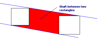 (Figure 1) Example of Shaft in 2d between 2 rectangles: (shaft.gif) Mapping visibility between two objects may seem like a waste, but lets see what we can do with it. Firstly, if there is NO lines left between the objects and we end up with a null result when we intersect the volumes in plücker space with the Grassman manifold, then obviously the two objects are never visible to each other. This can be used to find potential sets etc. Also, the radiosity equation has a visibility function in it. Often this is performed as a binary function (occlusion or no occlusion), but we can use these properties to find the function as a very accurate scalar between 0 and 1, producing much more accurate results. Also, we can use this to accelerate ray-tracing etc. A couple of other principles can also be used to exploit this. For example, if we can find line segment uninterrupted by occlusion between two faces, all the volumes/portals this line stabs are visible to each other. |
|
Portal PVS In Plücker Space
|
|
Note, if you wanted to find a semi accurate portal based PVS ala quake, you could simply use propagation and clipping to planer anti-penumbra of portals. You could use ray jitter (Harmless tells me this is what QuakeX uses) or you could use extended S-buffer projection. However, these tests are all fairly inaccurate. And apart from ray jitter, none of them allow for quadric visibility bounds. But, we can again use our linespace structure to find visibility. For each sector, we do this; For every portal in the sector, we make a line space structure defining all the lines which pass through it. Then, we re-curse to all portals in the connecting sector like so; We find the union between the linespace structure passed through by recursion, and linespace structure of the portal we have re-cursed to. If after the union operation we find a null structure, then the visibility recursion is ended, and the portal is not potentially visible. Otherwise the portal is potentially visible and recursion is continued. Here is some pseudo C++ code for such an operation;
This is just to help you get a feel for doing such operations. Note, that this is pretty much theory, and unless you have time to make lengthy PVSs, it is not really for you. Another way to do a PVS in plücker space is to find if a line stabs a set of portals (this line is known as a site line). A test developed by Teller can be performed in plücker space to test this. This test however suffers numerical degeneracies. Scaling of the portals by 1+epsilon can work well. Also, note that we can restrict this test to extremal stabbing lines, as if a line stabs the set, one of the extremal stabbing lines of the set must also stab it. Using this test, we can re-use previous extreme stabbing lines and pre-test if the said line intersects other portals, to make for a lazy calculation test. The lazy calculation test is good in that it can avoid calculation by a quick test which marks the node as visible (the line has stabbed it) without going on to the full lengthy process required. |
|
Related Links & References
|
|
Seth Teller's publication page (which contains multiple on topic publications): http://graphics.lcs.mit.edu/~seth/pubs/pubs.html Fredo Durand's Homepage (Which also contains many good publications): http://graphics.lcs.mit.edu/~fredo/ And George Drettakis's publications page: http://www.flipcode.com/dp/issue02.shtml |
|
Conor Go Bye Bye Now
|
|
Okay, this column was just to go through some visibility theory, often very hard to understand stuff. If you got this far you've done well, if you didn't understand don’t worry, read it again. Anyway, next week I hope to actually get to more practical visibility. Remember, save an orphan/stepchild, beat an umpa lumpa. Conor "DirtyPunk" Stokes |