|
Building a 3D Portal Engine - Issue 12 - Collision Detection (Guest Writer) by Jaap Suter (19 March 1999) |
Return to The Archives |
Introduction
 |
|
Welcome back to the Portal Column. This edition is a special one: It is not written by The Phantom this week because we have our first 'guest' column writer: Jaap Suter! Of course his style is completely different, but he presents some good solid information. Make sure you let him know what you think of his article using the portal column messageboard! A beginners explanation of 3 dimensional collision detection I remember the day I wrote my first 3D engine like it was yesterday. After 2 months of coding and debugging I finally decided the engine was finished and it was time to create a game. It wasn’t until then that I realized there is not much of a game if you can walk and shoot through the walls. Later on I realized there is no such thing as a finished 3D engine, but that’s a story for another day. What will be explained hereafter is the algorithm I thought up that day to stop me from walking through walls. This so called "bounding sphere" algorithm is one of the simplest among collision detection algorithms but can be extended to more complex ones relatively simply. I will come back to that later. Math: First of all we need some math. Since you got your texture mapped, 3d clipped, z buffered, gouraud shaded engine already up and running, I will assume you know all the basics and theories behind the formulas proposed here. Equation 1: 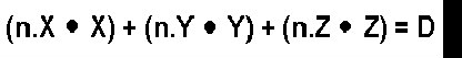 If vector n is the normal of a face consisting of three components (n.X, n.Y, n.Z) and D is a real number then every coordinate (X, Y, Z) that completes this equation is said to lie in the infinite plane that has normal n and the absolute value of D as the shortest distance from the plane to (0, 0, 0). I think this formula is very familiar cause any, even the simplest, 3D engine cannot live without it. Let’s rewrite the equation a little: Formula 1: 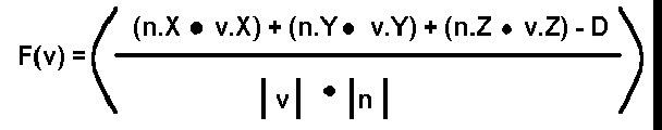 In this formula the denominator stands for the length of vector v times the length of the normal. The length of a vector is calculated as follows: Formula 2: 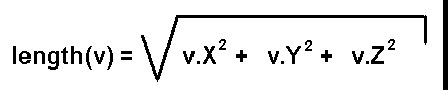 But you probably already knew that. Now what the heck does this formula 1 (not 2) do, you might wonder. Well it returns the shortest distance from point v to the plane described by n and D. Just make sure you don’t want to know the distance from (0, 0, 0) to the plane cause you will get some nasty divide by zeros. Besides D is the distance from the 0 vector to the plane. The optimizer is already sweating I see. One slow division and two even slower square roots. You definitely don’t want to do square roots in realtime. -Not even when you’re called the Phantom- So let’s do some tricky stuff here. Why not precalculate the normals of you faces and divide them by there own length so they all have length one. That way you loze the divide and you can precalculate the square roots. If the normals have length one then formula 1 changes into: Formula 3:  Mmmmm not that tricky after all. But the result is pretty neat, just three muls, two additions and one substraction. Let’s see how this all applies to collision detection. Collision detection: Remember that the algorithm presented was called the bounding sphere algorithm. This means that everything that moves in your engine (a mesh) is modeled as a sphere when detecting collisions. This means it is not a very good algorithm for colliding humans. I will come back to that later. How do you construct such a sphere? First of all define a point of rotation for the mesh, this will be the center of the sphere. Then find the average of all the distances from the vertices of the mesh to that centerpoint. That average is the radius of the bounding sphere. Once you have the bounding sphere you can detect colissions fairly easy. Suppose you have a very very simple world consisting only of a plane and a mesh. In this picture I already calculated the bounding sphere of the mesh and displayed it: 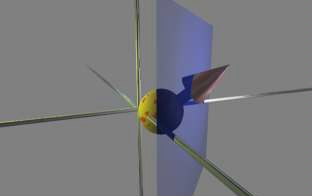 I made an arrow point outwards the sphere 'cause that is where the sphere is going to move the next frame (in our 3D engine). The blue transparent plane is the plane I described. As you can see the arrow cuts trough the plane so probably our sphere has collided with the plane in between this frame and the next frame. How can we detect this collision? Let’s say the sphere is at (1, 1, 0) and it moves over the arrow to (4, 4, 4). The blue plane has a normal (-1, -1, 0) and a D = 2. First we must normalize (make length one) the normal of the plane. This is done by using formula 2 and dividing every component by the length of the normal (precalculate!!). So the new normal of the plane is: (0,7071; 0,7071; 0). These values are rounded but again you should not round them 'cause what do we have floats for? If we then fill in formula 3 for both frames. That means for the sphere at v1: (1, 1, 1) and at v2: (4, 4, 4) then: 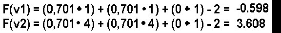 As you can see in between the frames the sign of the outcome has changed. This means the sphere went from one side of the plane to the other side. So that means a collision has happened. A second possibility is you move the sphere from v1: (1, 1, 1) over the arrow to v3: (1.2, 1.2, 1.2). In that case formula 3 applied on v3 gives us:  Now the sign has not changed. But suppose the radius of the bounding sphere is 0,5 units. Then the distance from the centerpoint to the plane is smaller then the radius and this means the sphere is intersecting the plane. A collision is detected so appropriate action should be taken. I will come to collision handling later. What a beautiful world we would live in if everything would consist of inifinite planes. Too bad it ain't. With the described method above you can only detect collisions with infinite planes. Our 3Dengine worlds usually contains finite planes so let’s do something about that. I assume your 3Dengine renders only triangles but the described method can easily be extended to more than three sided poly’s. Since a triangle is a finite plane we are going to detect collisions with triangles. Take a look at this picture: 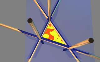 The red and yellow triangle is the triangle in our 3Dengine world. The four blue planes are the planes to test. One of them you already saw. It’s just the infintie plane right trough the triangle. The other three are perpendicular to the triangle and go trough one side of the triangle each. Then when collision detecting you first check it agains the infinite plane of the triangle itself. If nothing happened, you're ok and continue with checking on other triangles. If a collision with the infinite plane did occur you check the bounding sphere against the planes that are perpendicular to the triangle. In this way you check against the triangle only. If the boundingsphere is on the inside of all perpendicular planes than the sphere did collide. How do you construct those perpendicular planes? Well first you take the cross-product of the normal and the edge vector. Then you normalize it and construct formula 3. Then you fill in the third point (the one that is not one point on the side). The outcome should be positive. If that is not the case you should negate the normal. Collision handling: Now you are able to detect collisions against triangles you should also handle them. What I will explain here is a technique called sliding and it is the most used technique. It means that if you run into a wall you slide parralel to the wall in the direction you were facing. Note that if you run in the wall hundred percent perpendicular, nothing happens. How can this be achieved? The outcome of the new position is very important. When moving the sphere from an old position to a new position and a collision is detected then the sphere should be put back somehow so that the sphere is at a valid place. This can be achieved in the following way. The distance from the sphere to the plane is calculated when collision detecting on a new position. The sphere’s radius minus this calculated distance is the distance the sphere should be put back. Divide this distance by the plane normal lenght and move the sphere that much times over the plane normal. Then the sphere is right against the plane. A picture should clarify this: 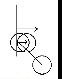 As you can see in this 2 dimensional picture the sphere first collided with the wall and was then put back over the normal of the plane. This should be enough to implement you own collision handling algorithm. But let’s make things a little bit faster first. Optimizations: If there is one thing I do not know much about relating to computer games and 3D engines programming it is optimizing. I can see the difference between a bubble and a quick sort but that’s about it. Therefore I cannot tell you much about optimizing this collision detection algorithm. There is however a very obvious optimization which is the following: Combine backface culling and collision detection. When you are backface culling you already use the point to plane distance formula (formula 3). That time you only needed it for the sign and discarded the distance. Why not store it somewhere and use it again for collision detection? Bounding sphere and beyond: The presented algorithm works best for meshes that come close to a sphere. For human bodies it does not work very well. What you can do is check for a large sphere surrounding the entire mesh and test colliding faces with smaller bouding spheres. (for example: one for the head, one for the torso and one for the legs.) If you still need better collision detection you should do a look into the bounding box algorithm. Maybe I’ll write about it some other time. And if you’re a real hotshot? Do a search for rigid body dynamics on any search machine. Conclusion: I tried to explain the bounding sphere algorithm for colission detection and handling. It works well for close to sphere meshes and is very fast, especially in combination with backface culling. There are however way more advanced algorithms that should do the job better. But that is for the next time. (If there will be a next time?) (yes there will - Phantom:) Anyway, code clean, play GoldenEye and go vegetarian! Seeya! |